

 咨询热线
咨询热线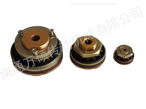
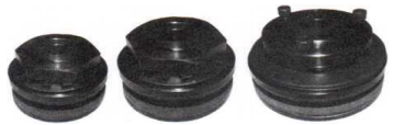
TLA摩擦式扭矩限制器
PDF下载
产品描述
TLA摩擦式扭矩限制器
♦奔万扭力限制器是一种扭矩过载保护装置。在机 器负载震动,超载或机械故障而致所需之扭力超过设定 值时,它以滑动方式限制传动系统所传动之扭力,而于 ,超载情形消失后自动啮合,不必再行设定。奔万扭力限 制器能有效的防止机械损坏,避免了昂贵的停机损失。
Benwan torque limiter is a protective device which limits the torque transmitted in a drive system by slipping when the d- emanded torque exceeds a preset value as a result of shock loads, overloads or machine jams.lt will automatically reengage when the overload is removed.No resetting is required.
♦奔万扭力限制器釆用弹簧负荷式摩擦表面,以螺帽或螺栓调整弹簧力,预设其滑动力
Benwan torque limiter utilizes spring-loaded friction surfaces for its operation ; and slip toque is preset by adjusting the spring force with nuts and bolts.
♦奔万扭力限制器可以用链轮、齿轮、槽轮或法兰板作为中心构件,夹在其摩擦面中间。奔万扭力限制器性能 可靠,与是适合的弹簧负荷和表面压力相一致结合,保证了较长的打滑时间,提供永久性的保护,本扭力限制器不 似剪销式机械一次使用就须作废,而是可以重复使用。
Benwan torque limiter can be used with a sprockets, gear, sheave or flange plate as the central member clamped between two friction facings.Benwan torque limiter ratings are realistic and consistent with optimum spring loads and face pressures that e- nsure longer slip time.maintain reengage ment at preset provide long protection.This is an important advantage over the shearpin mechanism which serves only as one-shot remedy.
。选择方法seletion
♦从负荷条件或机器设计强度,决定所需滑动扭力。如机器负荷条件不详,则将扭力限制器滑动扭力设定为其 安装相关马达所产生之扭力1.5 - 2倍。
Determine the required slip torque according to the load conditions or the designed strength of the machine.lf the loading conditions of the machine are not clear> then set the required slip torque of the limiter to be 1.5 to 2 times of the torque when related motor is mounted.
♦请选择扭力范围和内径范围足够的扭力限制器。
Select a torque limiter which has enough torque range and bore range.
♦衬环的长度由摩擦片间中心构件的厚度决定。构件的选择不可大于中心构件的厚度,中心构件的最大宽度见 表中 S〈最大〉栏
o Determine the proper bushing lengthaccording to the thickness of the central constitutes clamped between the friction faces.Always choose the bushing which does not exceed the width of the central constitutes.MAXimum width of the central constitutes is shown as column S ( max) in the table.
。中心构件 center member
♦中心构件之摩擦必须研磨加工以保证额定之扭力,以及平面度、平行度与内径相垂直,不含任何灰尘,铁皮 和油污,表面研磨度以3S-6S为宜。
The central constitutes should be grinded on its friction faces to ensure the rated torque and free of rust, scale and oil, and to make sure that flatness* parallel and internal diameter are vertical.The surface finish is recommended as 3S to 6S ( 63 microinches finish ) .If the central constitutes are not in accordance with these specifications, the slip torque will be erratic.
 |
TLA摩擦式扭矩限制器
扭力限制器的设定只需扭紧或放松调整螺栓/或调整螺帽便可,TLA200至TLA350型各具一调整螺帽,TLA500至TLA20型则各具调整螺栓供扭力调 整用。
Torque setting of the Torque Limiter is achieved by tightening or loosening the adjustment bolts and / or the adjustment nuts.For KRTL200 to TLA350, an adjustment nut is provided, and for TLA500 to TLA20, adjustment bolts are provided.
扭力限制器在安装至轴上后,即可进行扭力调整,其步骤如下:
The torque setting can be made after mounting the Torque Limiter on the shaft. The steps are as below: For TLA200 to TLA350:
首先,用手以全力转动 调整螺帽使碟形弹簧固定至一压板。然后,暂时以一扳钳把螺帽拧紧到60度。
Firstly, rotate the adjustment nut tightly by hand to flxthe disc spring in the plate. Then tentatively tighten the nut by about 60 degrees with a wrench. ForTLA500toTLA10, 14, 20:
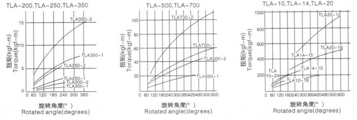
首先,转动一螺帽,把碟形弹簧固定至一压板,再将每一调整螺栓拧紧60度。其次,如于正常情况下扭力限制器仍然滑动,则逐渐拧紧螺帽 (TLA200-TLA350型)或螺栓(TLA500-TLA20型),一直到扭力限制器不再滑动。注意,各螺栓之松紧度必须均匀,先试行调整数次以求得相关机器之 正确扭力设定,下一页为有效旋转角度和预设扭力关系图可参考。为求精密扭力之调整,宜将本扭力限制器在扭矩调整后把螺帽或螺栓旋转45度, 于50-60RMP下度运转500回转。
Firstly, rotate the nut to fixing the disc spring in the plate, and then tighten each adjustment bolt by about 60 degrees. Then, if the Torque Limiter slips under normal loading conditions, gradually tighten the nut (for TLA200 to TLA350)or the bolts (for TLA 500 to TLA20) until the torque limiter stops slipping. Always tighten (or loosen) the bolts equally, try this adjustment several times to find the proper torque setting for the machine. For your guidance, the chart on the next page shows the relation between the effective rotated angle and preset torque. For precise torque setting, run-in of torque limiter is recommended. For example, 500
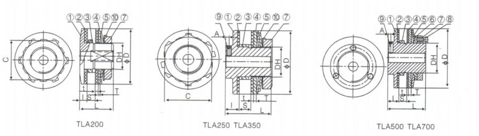 |
| 零件名称: Name of parts: ① 主体Hub ② 摩擦片 Friciton facing ③ 衬环Bushing ④ 压板 Pressure Plate |
⑤ 碟形弹簧Disc Spring ⑥ 导向压板Pilot Plate ⑦ 调节螺母Adjustment Nut ⑧ 调节螺栓Adjustment Bolt |
⑨ 锁紧螺钉SetScrew ⑩ 止退垫片Lock Washer |
BWTLA200~BWTLA700的尺寸表Dimensions and Capacity for -BWTLA200-BWTLA700
| 型号Model | 扭矩范围 Torque Range (Nm) |
最高转速 MAXspeed irbalancde rpm |
成品内孔 Finish Bore |
最大孔 径 MAX. Bore | 衬环长度 0. D. of Bushing |
衬环外径 0. D. of Bushing |
踊 Bore for center Member |
D | Dh | L | I | T | t | S (max.) |
A | C | 质量 Mass (Kg) |
调节螺栓 Adjust. Bolt |
| TL200-1 | 2. 9~9. 8 | 6600 | 8 | 14 | 3.8 | o-0. 020 | +0. 033 | 50 | M24 | 29 | 6. 5 | 2.5 | 36 | 0. 26 | ||||
| TL200-2 | 6. 9-20 | 6.0 | "0. 041 | 30 0 | 1.6 | 7 | ||||||||||||
| TL250-1 | 6. 9-27 | 4.5 | -0. 025 | +0. 039 U 0 |
||||||||||||||
| TL250-2 | 14-54 | 6600 | 10 | 22 | 8.0 | 41 -0. 050 |
65 | M35 | 48 | 16 | 4.0 | 3.2 | 9 | 4 | 50 | 0. 74 | ||
| TL350-1 | 20-74 | 6.0 | -0. 025 | +0. 039 | ||||||||||||||
| TL350-2 | 34-149 | 17 | 25 | 14.5 | 竺 0. 050 | 49 出0 |
89 | M42 | 62 | 19 | 4.0 | 3.2 | 16 | 5 | 65 | 2. 48 | ||
| TL500-1 | 47-210 | 2700 | 20 | 42 | 6.0 | -0. 030 | +0. 046 | 127 | M65 | 76 | 22 | 6.0 | 3.2 | 16 | 6 | 3. 85 | M8XP | |
| TL500-2 | 88-420 | 14.5 | 從 0. 060 | 74 0 | 1. 03pcs | |||||||||||||
| TL700-1 | 116-569 | 2100 | 30 | 64 | 8.0 | -0. 036 | +0. 054 | 178 | M95 | 98 | 24 | 7.0 | 3.2 | 29 | 6. 5 | 9.44 | M10XP | |
| TL700-2 | 223-1080 | 22.0 | 10-0. 071 | 105 q | 1. 03pcs |
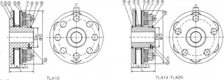 |
零件名称:Name of parts:
①主体Hub②摩擦片Friction③衬环Bushing④压板A Pressure Plate A⑤压板B Pressure Plate B
⑥碟型弹簧Disc Spring⑦碟型压板Disc Spring Plate⑧导向压板Pilot Plate®调节螺栓Adjustment Bolt
⑩轴用挡圈Snap Ring⑪外接圈Spirolox⑫弹簧栓Spring Pin
TLA10-TLA20 的尺寸表 Dimensions and Capacity for TLA10-TLA-20
| 型号 Model | 扭矩范围 Torque Range(Nm) |
最高转速 MAXspeed inbaiancd" rpm |
成品 内孔 Finish Bore |
最大孔径 MAX. Bore |
衬环长 度 Bushinc Length |
衬环外径 0. D. of Bushing |
中心原 件配合 孔径 Bore for center Member | D | Dh | L | I | Ti | T2 | t | S (max.) |
C | 质量 Mass (Kg) |
调节螺栓 Adjust. Bolt |
| TLA10-16 | 400-1240 | 1400 | 30 | 72 | 12.5 | ! 35 0 086 -0. 125 |
254 | 100 | 115 | 23 | 8.5 | - | 4.0 | 24 | 19 | 21 | M18X1.5 | |
| TLA10-24 | 590-1860 | 19.5 | ||||||||||||||||
| TLA14-10 | 890-2660 | 1200 | 40 | 100 | 19.5 | 185-° 0 : -0. 12 |
y | 356 | 145 | 150 | 31 | 13 | 13 | 4.0 | 29 | 27 | 52 | M26X1.5 |
| TLM4-15. | 1960-3920 | 23.5 | ||||||||||||||||
| TLA20-16 | 2450-4900 | 800 | 50 | 135 | 15.5 | -0. 12 | 22节 。。7 0 |
508 | 185 | 175 | 36 | 15 | 18 | 4.0 | 31 | 36 | 117 | M32X1.5 |
| TLA20-12 | 4610-9310 | 23.5 |
 |
订货描述示例:
旋转角度与预设扭力 rotated angle and setting torque
| TLA14-10 | 040 | 040 键槽04Okeyway |
| 规格与型号 Size/type of joint | 成品孔径 Finish bore (H7) |
成品孔径(H7)键槽按 G B/T3852 - 1997 (JS9)标准 Finish bore (H7) to GB/T3852-1997 (JS9) |